
90 degree flange rotary joints
90 degree flange rotary joint, 90 degree flange rotary joints, 90 degree flange rotary union, 90 degree flange rotary unions, 90 degree flange swivel joint, 90 degree flange swivel joints, 90 degree flange swivel union, 90 degree flange swivel unions
90 Degree Flange Rotary Joints: The Complete Design and Application Guide
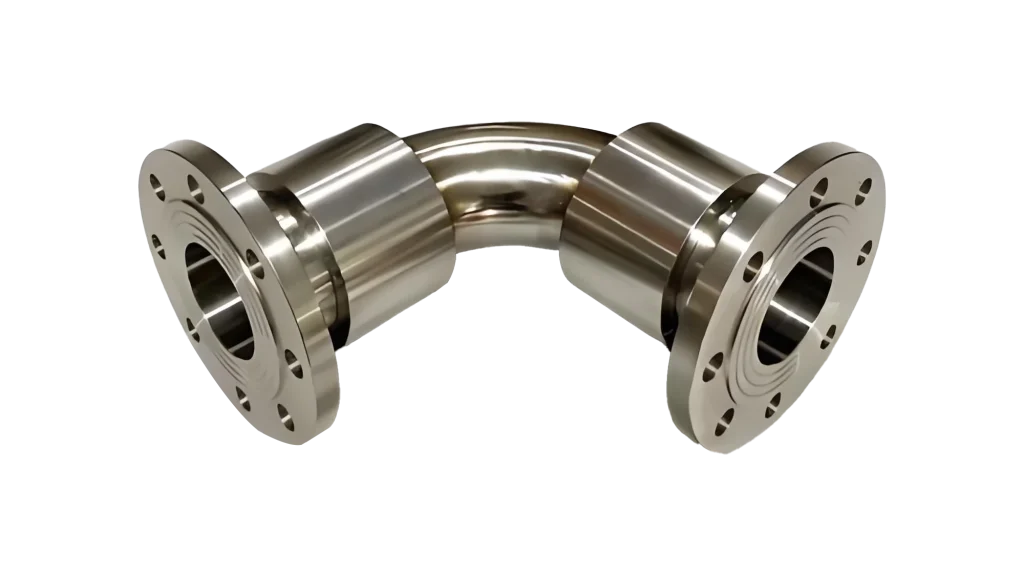
90 degree flange rotary joints are rotary couplings that transfer a fluid between a stationary supply pipe and a rotating machine part while redirecting the flow at a right angle. The “90 degree” term refers to the orientation of the flange connection, which sits perpendicular to the axis of rotation so that supply and return piping can approach from the side rather than from the end. The flanged connection itself provides a secure, high-integrity seal between the joint and the machine, which is why this design is so widely used on steam-heated dryers, hot-oil calenders, and water-cooled rolls.
These components sit at the interface between two worlds: a fixed piping system that never moves, and a roll, cylinder, or drum that rotates continuously at speed. They must keep the fluid contained at working temperature and pressure while the machine turns, often for years at a time. Because a failure here means a leak, a process stop, or worse, a steam or hot-oil release, choosing the right unit and maintaining it correctly is a safety and reliability decision, not just a purchasing decision.
This guide explains how the component works, what it is made of, the specifications that matter, and where it is used. It also covers selection, installation, and maintenance so that you can specify, fit, and care for the unit with confidence.
How a 90 Degree Flange Rotary Joint Works
The working principle is simple in concept but demanding in execution. Fluid enters through the stationary side of the flange connection, is redirected through a right-angle passage, and flows into the rotating shaft. From there it travels into the rotating roll or drum, transfers its heat or cooling effect, and returns through the same or a parallel passage. The flange connection bolts the unit firmly to the machine, while a precision seal inside allows the shaft to rotate without letting fluid escape.
Two mechanical systems work together inside the housing. A bearing assembly carries the radial and axial loads of the rotating shaft and keeps it centered, while a seal package—typically a wear-compensating carbon or graphite face seal backed by a spring—contains the fluid. The seal runs against a hardened, lapped face so that a thin fluid film forms a barrier between the rotating and stationary parts. This is the same principle used in mechanical seals throughout industry, adapted here to survive continuous rotation and thermal expansion.
The right-angle design matters for more than piping convenience. By bringing the connection in from the side, the joint can be mounted where there is no room for an end connection, such as between closely spaced rolls. It also keeps the supply piping clear of the rotating shaft and coupling, which makes installation and maintenance easier in crowded machine frames.
Condensate handling adds a further layer to the design on steam service. Because steam condenses inside the heated roll, the unit must also carry the condensate back out, usually through a siphon pipe that passes through the center of the rotating shaft. This means a single component can be responsible for supply, return, and sealing all at once, which is why the internal passages, siphon clearances, and drain arrangements are specified as carefully as the seal itself.
Detailed Product Description and Components
A typical unit is assembled from a small number of precision-machined parts. The body is a cast or machined housing, usually of carbon steel, ductile iron, or stainless steel, shaped to provide the right-angle flange port. The rotating shaft is supported on ball or roller bearings and carries the internal flow passages. At the interface between the stationary body and the rotating shaft sits the seal assembly, which is the heart of the component and the part most likely to need replacement during service.
The seal package consists of a rotating face and a stationary face held together by spring pressure. The faces are lapped flat to within a few light bands, hardened for wear resistance, and selected to suit the fluid. For steam service, carbon against a hardened steel face is common; for hot oil, graphite or PTFE-based materials are preferred. A secondary O-ring or gasket seals the static joints so that the only place fluid can possibly escape is the running seal face, which is designed for controlled, replaceable wear.
The flange is drilled to a standard bolt pattern—typically matching common DIN or ANSI flange sizes—so that the joint bolts directly to a mating flange on the machine. Because the flange carries the full weight and torque of the connection, it is machined flat and reinforced to resist distortion under bolt load. Quality units include a hardened shaft surface where the seal runs, a lubrication port for the bearing where applicable, and a drain or leakage port that carries any weepage safely away.
Material selection is driven almost entirely by the service. Carbon steel bodies offer a good balance of strength and cost for steam and water duty, ductile iron is often chosen for hot-oil service where thermal cycling is severe, and stainless steel is used in corrosive or hygienic applications. The seal faces are matched to the fluid as well, with carbon-graphite against hardened steel for steam, PTFE-based composites for hot oil, and ceramic or tungsten-carbide faces for the most abrasive or aggressive services. Getting this material combination right is what separates a unit that lasts for years from one that fails in months.
Key Design Features and Benefits
Right-angle flange connection. The 90-degree port orientation keeps supply piping clear of the shaft and allows mounting in tight spaces between rolls.
High-integrity flanged joint. A bolted flange provides a stronger, more serviceable connection than a threaded fitting, and it is less prone to loosening under vibration and thermal cycling.
Wear-compensating seal. A spring-loaded face seal takes up wear automatically, maintaining sealing force as the faces slowly wear, which extends the interval between replacements.
Hardened, lapped faces. Precision-lapped seal faces run with a thin fluid film that reduces friction and heat, improving seal life and reducing leakage.
Replaceable wear parts. The seal faces, springs, and O-rings are designed for field replacement, so the body can be refurbished without being scrapped.
Multiple media capability. With the right seal materials, the unit handles steam, thermal oil, hot water, and compatible process fluids across a wide temperature range.
Drain and leakage ports. Built-in ports carry any weepage safely away from the machine and make it easy to monitor seal condition.
Technical Specifications
The exact ratings depend on the model, size, and seal materials, but the table below summarizes the typical performance envelope for this class of component.
| Parameter | Specification | Notes |
| Connection orientation | 90 degree flange | Perpendicular to rotation axis |
| Flange standard | DIN / ANSI | Common nominal sizes |
| Working pressure | 0.5 – 2.5 MPa | Steam and hot oil service |
| Maximum temperature | up to 350°C | With high-temperature seals |
| Rotation speed | up to 300 rpm | Size dependent |
| Compatible media | Steam, thermal oil, hot water | Seal material dependent |
| Body material | Carbon steel, ductile iron, stainless | Application dependent |
| Seal material | Carbon, graphite, PTFE | Selected for fluid and temperature |
| Shaft diameter | 15 – 150 mm | Nominal bore sizes |
| Allowable leakage | minimal weepage | Normal for running seals |
Because exact limits vary by model, always confirm the pressure, temperature, and speed ratings against the manufacturer’s data sheet before specifying a unit. Running beyond a rating shortens seal life sharply, so a safety margin of at least ten to twenty percent above the normal operating point is good practice.
Typical Applications and Use Scenarios
The component appears wherever a rotating roll or drum must be heated or cooled through a flanged connection. Common applications include:
- Steam-heated dryer cylinders in paper and board machines, where steam enters through the flange and condensate is removed through the same unit
- Hot-oil calenders in plastics and rubber processing, where thermal oil heats the rolls to a precise temperature for sheet thickness and finish
- Water-cooled rolls in film and coating lines, where chilled water removes heat from the roll surface
- Textile finishing machines where steam or hot oil heats drying and setting cylinders
- Corrugator preheaters and pressure rolls in board manufacturing
- Laminating and embossing rolls that require controlled surface temperature
In a paper dryer section, for example, the component bolts to the dryer journal with the flange oriented to the side, so that steam piping runs along the machine frame rather than projecting from the roll end. Steam enters, condenses against the inside of the shell, and the resulting condensate is removed through a siphon inside the rotating shaft. The same unit must seal against steam pressure, cope with the thermal expansion of the dryer, and run for months between shutdowns—a demanding combination that the right-angle flanged design handles well.
In a hot-oil calender, by contrast, the component carries thermal oil at 250°C to 350°C into a precision-ground roll that must hold its surface temperature to within a degree or two. The right-angle flange lets the oil piping run neatly along the calender frame, and the seal must hold against both high temperature and the thermal expansion of the rolls as the machine comes up to temperature. Regular inspection of the drain port catches any seal weepage early, before it can contaminate the product or the surrounding machinery.
How to Select the Right Model
Match the flange standard and size. Confirm the bolt pattern, pressure rating, and nominal bore against the machine’s mating flange to ensure a drop-in fit.
Confirm pressure and temperature. Check the maximum steam or oil pressure and temperature, and select a seal material rated for that duty plus a safety margin.
Verify speed and rotation. Make sure the rated rotation speed matches the machine, and confirm the direction of rotation if the seal is handed.
Identify the media. Steam, thermal oil, and water each require different seal materials and body metals, so state the fluid clearly when ordering.
Check for siphon or return needs. On steam-heated rolls, decide whether a condensate siphon must pass through the shaft, and specify it accordingly.
Plan for service. Choose a unit with replaceable seals and confirm spare-parts availability so maintenance stays simple.
Installation and Maintenance Tips
Bolt up squarely. Draw the flange bolts down evenly and in sequence so the joint seats flat and the seal is not distorted by uneven clamping.
Allow for thermal expansion. Mount the unit so the shaft can move slightly with the machine as it heats, rather than being rigidly constrained.
Monitor weepage. A small amount of weepage from the drain port is normal; a sudden increase signals worn seals that need attention.
Replace seals on schedule. Change the seal faces and springs during planned shutdowns before they fail outright, which prevents unexpected leaks.
Keep steam traps and condensate drains clear. On steam service, a blocked return can flood the roll and damage the seal.
Protect idle units. If a roll sits unused for long periods, rotate or purge the unit occasionally to prevent the seal faces from sticking or corroding together.
Common Failure Modes and How to Avoid Them
Seal wear. Normal friction gradually erodes the faces. Scheduled seal replacement avoids sudden leakage.
Thermal shock. Sudden temperature changes can crack or distort the seal faces. Warm the unit gradually during startup.
Flange leakage. Uneven bolt tightening or a damaged gasket causes leaks at the static joint. Torque bolts evenly and replace gaskets during service.
Bearing failure. Contamination or inadequate lubrication shortens bearing life. Keep bearings clean and lubricated to specification.
Corrosion and erosion. The wrong body material for the fluid can corrode or erode internally. Match materials to the media.
FAQ
What is this type of rotary joint used for? It transfers steam, thermal oil, or water into a rotating roll or drum through a side-mounted flange connection, keeping the supply piping clear of the rotating shaft.
Why use a flange instead of a threaded connection? A bolted flange is stronger, easier to service, and more resistant to loosening under vibration and thermal cycling than a threaded fitting.
What fluids can these units handle? Steam, thermal oil, and hot water are the most common, with the seal and body materials selected to suit the specific fluid and temperature.
How do I know when to replace the seals? A sudden increase in weepage from the drain port, or visible leakage at the running face, indicates that the seal faces have worn and should be replaced.
Can these units be repaired? Yes. Because the seal faces, springs, and gaskets are replaceable, a worn unit can be refurbished in the field at a fraction of the cost of a new one.
What flange standards are available? Common DIN and ANSI flange patterns are standard, and custom bolt patterns can usually be supplied to match existing machine flanges.
Conclusion
Choosing the right 90 degree flange rotary joints comes down to matching the flange, pressure, temperature, and media to the machine, then maintaining the unit with even bolt-up, gradual warm-up, and scheduled seal replacement. A well-chosen and well-cared-for unit runs quietly for years at the heart of a dryer, calender, or cooling roll, while a neglected one leaks, damages surrounding equipment, and forces costly downtime. Understanding how these components work and how to specify them is the surest way to keep rotating equipment running safely and efficiently.