
High speed hydraulic rotary joint
High speed hydraulic rotary joint, High speed hydraulic rotary joints, High speed hydraulic rotary union, High speed hydraulic rotary unions, High speed hydraulic swivel union, High speed hydraulic swivel unions, High speed hydraulic swivel joint, High speed hydraulic swivel joints
High Speed Hydraulic Rotary Joint: Design, Specs, and Applications
When a hydraulic circuit must feed a cylinder, motor, or actuator that spins at hundreds or thousands of rpm, a standard hydraulic rotary joint will not survive. The seals overheat, the faces wear rapidly, and the bearing fails within hours. A high speed hydraulic rotary joint is engineered for this service, with balanced seal geometry, low-friction face materials, precision bearings, and dynamic balancing that keep the unit stable at the upper end of its speed range.
The same architecture is used wherever a rotating hydraulic actuator or workholding fixture needs continuous power transfer without twisting the hose. Compared with a standard union, a high speed model adds features that manage centrifugal load, friction heat, and vibration, so the machine can run three shifts without unplanned downtime. Whether the application is a high-speed rotary indexer, a tire-curing press, a paper machine calender, or a high-rpm machine tool spindle, the device keeps oil flowing steadily through unlimited 360-degree rotation.
This guide covers how the unit is built, what design features set it apart, the top use cases that benefit from high-speed performance, and the practical steps for selecting, installing, and maintaining it.
How a High Speed Hydraulic Rotary Joint Works
The unit is essentially a precision swivel with three coordinated systems: a hydraulic seal package, a precision bearing set, and a balanced rotating member. The hydraulic side handles the working medium—typically mineral oil, water-glycol, or a compatible fluid—through a stationary inlet and a rotating outlet that can spin without limit. The seal faces are precision-ground and lapped to a flatness measured in light bands, so the contact area stays uniform as the joint rotates at speed.
Inside the body, the bearing supports the rotating member and keeps the seal faces perfectly concentric under centrifugal load. A vented housing lets any small amount of fluid that bypasses the primary seal drain away safely. The result is a balanced assembly that can spin continuously while delivering clean, pressure-stable oil and holding tight leakage limits.
Modern high-speed designs use balanced seal geometry so system pressure loads the seal faces in proportion. This pressure compensation is one of the main reasons a well-engineered unit can hold tens of megapascals while rotating at thousands of rpm. Combined with low-friction face materials and a dynamically balanced rotor, the design keeps seal-generated heat low enough that the unit can run for years between planned services.
Why High-Speed Operation Demands Special Design
Speed introduces three forces a standard hydraulic union cannot manage: centrifugal loading on the rotating mass, friction heat at the seal interface, and dynamic imbalance that excites vibration. Centrifugal loading pushes the rotating member outward, increasing side load on the bearing and deflecting the rotor enough to open a clearance gap. Friction heat raises oil and elastomer temperature. Dynamic imbalance magnifies with the square of speed and can damage the bearing, the housing, and the driven member.
A high-speed design addresses each challenge. The rotor is precision-balanced to within a few gram-millimeters. The bearing is selected for high-speed service, often with ceramic balls or specialized lubrication. The seal faces use hard, low-friction materials such as silicon carbide against carbon graphite. The housing is rigid enough to hold the rotor in alignment. Together these features let the unit operate where a standard joint would fail within hours.
Detailed Product Description and Components
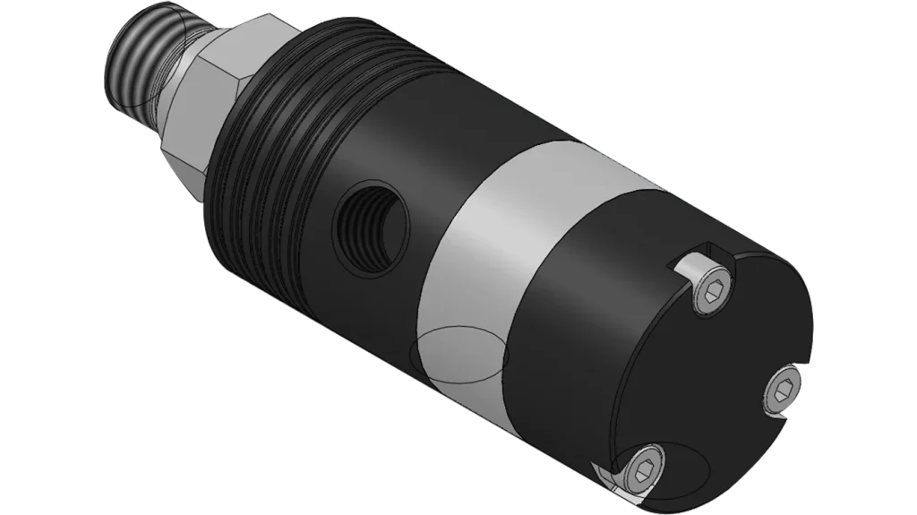
A quality version of this device is a compact, modular unit that integrates hydraulic channels, precision bearings, balanced seal elements, and a dynamically balanced rotor into a single machined housing. The stationary housing carries the inlet port, a mounting flange or threaded body, and a drain port. The rotating member carries the outlet port, a precision bearing journal, and a seal face carrier that is precision-ground and lapped to specification. The seal faces are typically silicon carbide against carbon graphite. The bearing is usually a high-precision ABEC-7 or ABEC-9 grade ball bearing, frequently with ceramic balls, lubricated with a low-viscosity grease or oil-mist. The rotor is dynamically balanced, with residual imbalance typically held to within G2.5 or G1.0 grade. Together these components form an integrated assembly small enough to mount on a high-rpm spindle yet robust enough for three-shift production at thousands of rpm.
Key Design Features and Benefits
Dynamically balanced rotor. Precision-balanced to keep vibration within tight limits at the rated speed, protecting the bearing, housing, and driven member.
High-speed bearing package. Precision ball bearings, often with ceramic balls and low-viscosity lubrication, support the rotor at full rated speed with low heat generation.
Low-friction seal faces. Silicon carbide against carbon graphite keeps friction and seal-generated heat low, so the seal can survive long runs at high rpm.
Balanced seal geometry. System pressure loads the seal faces in proportion, so leakage stays low and seal life stays long.
Rigid housing. A precision-machined housing holds the rotor in alignment under centrifugal load, maintaining seal concentricity at full speed.
Vented drain path. Any small amount of fluid that bypasses the primary seal drains safely away.
High-pressure capability. Engineered for working pressures up to 35 MPa or higher.
Long service life at speed. Balanced design, hard face materials, and a quality bearing let the unit run for years between services.
Technical Specifications
Its ratings cover pressure, speed, temperature, channels, and media, all of which must be matched to the system it serves. Typical performance ranges for industrial service include the following:
Its ratings cover pressure, speed, temperature, channels, and media, all of which must be matched to the system it serves. Typical performance ranges for industrial service include the following:
| Parameter | Typical Range / Value | Notes |
| Series | Standard / high-speed / ultra-high-speed | Matched to the application duty |
| Working pressure | 10 MPa to 35 MPa | Higher pressures available on special order |
| Rotation speed | 500 to 10,000+ rpm | Continuous rating, with peaks up to 15,000 rpm |
| Fluid temperature | -20°C to +120°C | Higher temperatures available on special order |
| Number of channels | 1 to 4 | Multi-passage designs route independent circuits |
| Media | mineral oil, water-glycol, synthetic fluids | Filtered to ISO 4406 18/16/13 or better |
| Body materials | hardened alloy steel, optional stainless | Stainless for corrosive environments |
| Seal face materials | silicon carbide vs carbon graphite | Tungsten carbide optional for shock loading |
| Bearing grade | ABEC-7 to ABEC-9 | Ceramic balls for highest speeds |
| Balance grade | G2.5 or G1.0 | Lower grade for higher speed |
| Connection types | threaded, flanged, manifold | Common thread sizes stocked |
| Service life | 8,000 to 25,000 hours at rated speed | Depends on pressure, media, and speed |
Because exact limits vary by model, always confirm pressure, speed, temperature, and balance grade against the manufacturer’s data sheet. Running beyond a rating shortens seal and bearing life, so a safety margin of at least 20 percent below the maximum rated speed is good practice.
Top 9 Applications and Use Scenarios
The combination of continuous rotation, high pressure, and high speed makes this device useful across a wide range of rotating machinery. The nine applications below cover the most common industrial uses, from machine tools and tire manufacturing to printing and packaging.
1. High-speed rotary indexers. Pneumatic-over-hydraulic clamps and rotary actuators need both speed and pressure.
2. Machine tool spindles. Hydraulic tool changing, through-spindle coolant, and clamping pass through one rotating interface on a high-rpm machining center.
3. Tire-curing presses. The mold rotates during curing, and hydraulic clamping, heating, and actuation circuits must reach the rotating mold through a high-speed, high-pressure joint.
4. Paper machine calenders. The calender roll rotates at moderate to high speed while needing steady hydraulic pressure for nip loading.
5. Printing cylinders. Hydraulic ink-feed, doctor-blade loading, and impression setting pass through one rotating interface on a high-speed printing press.
6. Packaging machinery. Form-fill-seal machines, rotary fillers, and labelers need hydraulic actuation and continuous high-rpm rotation in one envelope.
7. Rotary blow molding. Mold clamps and hydraulic actuation pass through a swivel that holds pressure at the high cyclic speed of a rotary blow molder.
8. Plastic film and sheet lines. Winder and unwinder rolls rotate at high speed while needing steady hydraulic pressure for tension control and brake loading.
9. Test rigs and dynamometers. High-rpm test rigs need hydraulic and signal wiring to actuators on a spinning fixture.
In each case, the device lets hydraulic actuators perform work while the assembly rotates, removing the need for complex hose arrangements that would otherwise twist, bind, and fail. The common thread is continuous rotation at high rpm combined with high-pressure hydraulic service, a combination only a purpose-built design can handle reliably.
Common Configurations
Single-channel units are the most common and least expensive, used when only one hydraulic circuit is needed. Dual-channel and multi-channel models route independent circuits through the same housing, useful when one circuit supplies clamping while another handles actuation or cooling. Higher speed ratings are available in balanced models with ceramic-bearing upgrades. Custom port orientations, special thread standards, and stainless steel bodies are available for washdown, hygienic, or corrosive environments, and most suppliers offer a configure-to-order path.
How to Select the Right Model
Confirm the duty cycle. Continuous high speed is far more demanding than intermittent high speed.
Match the pressure rating. System pressure including spikes must be within the unit’s rating, with a safety margin of at least 20 percent below the maximum.
Select the right balance grade. Higher speeds need tighter balance grades, often G1.0 rather than G2.5. Confirm the balance grade when the speed exceeds 3,000 rpm.
Confirm the bearing type. Standard bearings handle most applications, but continuous speeds above 5,000 rpm usually need ceramic-ball bearings and special lubrication.
Match the environment. Standard steel bodies handle most industrial duty; washdown, hygienic, or corrosive environments need stainless steel.
Plan for service. Choose a model with replaceable seals and bearings, and confirm spare-parts availability.
Installation and Maintenance
Align the housing carefully. Side load from misalignment is a leading cause of premature wear. Mount the unit on a flat, rigid surface and align the rotating shaft with the driven member before tightening.
Filter the fluid. Install a 3 µm (or finer) particulate filter upstream, and maintain it on schedule. Clean fluid is the most cost-effective step in extending service life at high speed.
Torque the mounting bolts evenly. Uneven bolt load distorts the flange and bearing preload. Follow the manufacturer’s torque sequence.
Warm up gradually. Cold-start at full speed generates thermal shock in the seal faces. Run at low speed for the first few minutes, then ramp up.
Monitor the temperature. A rise in housing temperature is often the first sign of seal wear or bearing distress. Install a temperature sensor for continuous service.
Schedule seal and bearing service. Plan a seal and bearing inspection at the manufacturer’s recommended interval, even if the unit appears normal.
Common Failure Modes
Seal face wear. The most common failure mode at high speed. Caused by fluid contamination, thermal cycling, or running beyond rated pressure. Filter the fluid, monitor temperature, and replace seals on schedule.
Bearing failure. Caused by side load, vibration, contamination, or lubrication breakdown. Replace the bearing and check alignment before returning the unit to service.
Rotor imbalance. Caused by material loss, fluid ingress, or original build error. Re-balance the rotor, or replace the rotating member.
External leakage. Caused by seal wear, overpressure, or pressure spikes. Confirm the pressure rating, install surge protection, and replace seals.
Housing distortion. Caused by uneven bolt load, side load, or thermal stress. Re-machine the mounting surface and follow the torque sequence.
FAQ
What speed counts as high speed for a hydraulic rotary joint? Speeds above roughly 500 rpm are typically considered high speed, with ultra-high-speed models reaching 10,000 rpm or more.
What is the most important design feature at high speed? Dynamic balance of the rotor, because imbalance magnifies with the square of speed and is the leading cause of vibration, bearing failure, and seal wear.
Can a high speed unit be used at low speed? Yes. Running below the rated speed is generally fine, but the cost premium is wasted on a low-speed application.
How long does the unit last at high speed? Service life typically ranges from 8,000 to 25,000 hours at continuous rated speed.
Can the seals be replaced without removing the rotor? In most designs yes. The seal elements are accessible through a service cover or by removing a retaining ring.
What is the most important preventive measure? Keeping the fluid clean. Clean fluid, matched seals, and a written maintenance schedule prevent the great majority of high-speed failures.
Conclusion
Choosing the right high speed hydraulic rotary joint is about matching the unit’s pressure, speed, balance grade, and bearing type to the machine it serves. Confirm the duty cycle, match the pressure rating, select the right balance grade, and verify the bearing type for the actual continuous speed. Once installed, keep the fluid clean, align the unit carefully, warm up gradually, and monitor the housing temperature as an early indicator of seal or bearing wear.
By understanding how the unit works, what features set it apart from a standard joint, and how to install and maintain it, engineers can keep high-rpm hydraulic equipment running smoothly and reliably for years. Whether the application is a machine tool spindle, a tire-curing press, a high-speed indexer, or a paper machine calender, the same fundamental principles apply: match the ratings, protect the seals and bearings, and service the unit before it fails. Spending a little time up front to specify the unit correctly, and a little effort in service to keep the fluid clean and the seals fresh, is almost always the most profitable decision a maintenance team can make.